

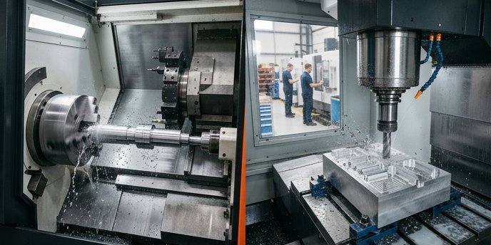
TL;DR: CNC turning rotates the workpiece against a stationary cutting tool and is optimal for cylindrical parts. CNC milling rotates the tool against a stationary workpiece and is optimal for prismatic geometry. Turning generally runs cheaper per hour, but combining both processes in a mill-turn machine cuts out the tolerance errors you get when a part moves between two setups.
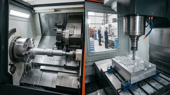
The Core Mechanical Difference (In One Diagram)
CNC turning spins the workpiece while a stationary cutter feeds into it. CNC milling does the opposite: the workpiece sits still while a multi-point tool spins and carves material away.
That mechanical flip is what dictates the coordinate system of each machine. Under ISO 841, the Z-axis is always parallel to the principal machine spindle. On a lathe, Z runs horizontally down the length of the part. On a vertical machining center, Z plunges down into the part. Same letter, totally different direction, and this trips up a lot of people new to G-code.
Workholding differs just as fundamentally. Turning uses chucks or collets that grip bar stock symmetrically so it stays balanced at speeds often north of 3,000 RPM. Milling uses vises, step clamps, or custom fixtures bolted to a T-slot table, holding irregular shapes rigid against heavy sideways cutting forces.
Which Part Shapes Belong on Which Machine
Turning for axisymmetric parts, milling for prismatic parts, mill-turn when you have both.
Axisymmetric parts (Turning): Anything built around a central axis belongs on a lathe. Shafts, pins, spacers, flanges, threaded fittings. If you can draw the part profile as a 2D cross-section and revolve it 360 degrees around a center line, it’s a turning job.
Prismatic parts (Milling): Flat surfaces, rectangular profiles, complex 3D contours. Engine manifolds, electronic housings, structural brackets, mold cavities. If material has to come off multiple flat planes, you need a 3-axis or 5-axis mill.
Hybrid parts (Mill-Turn or Multi-Setup): A cylindrical shaft with a flat keyway, a round flange with an off-center bolt hole pattern. These have both axisymmetric and prismatic features, which means either a two-machine workflow (turn the OD, then move to a mill for the keyway) or a single setup on a mill-turn center.
| Geometry Type | Defining Characteristic | Recommended Process | Example Parts |
|---|---|---|---|
| Axisymmetric | Revolved around a center axis | CNC Turning | Shafts, pins, flanges, nozzles |
| Prismatic | Flat planes, rectangular bounds | CNC Milling | Brackets, housings, manifolds |
| Hybrid | Cylindrical base with flats/holes | Mill-Turn / Multi-setup | Camshafts, custom fittings |
Cost per Feature, Not Cost per Hour
Comparing the hourly rate of a lathe to a mill doesn’t tell you what the part will actually cost. Anecdotally, in 2025 standard 2-axis turning runs around $75/hr and 3-axis milling around $85/hr, with 5-axis and mill-turn north of $130/hr (these numbers drift with regional capacity, so take them as ballpark). What matters is cost per feature.
Take a 2-inch diameter aluminum shaft that needs a 0.5-inch cross-hole.
Machine it entirely on a mill from square bar stock and the machine has to interpolate the entire 2-inch OD. Heavy material removal, long cycle. Machine it on a 2-axis lathe and the OD takes seconds, but the cross-hole requires a secondary operation: unchuck the part, move to a mill, indicate the center, drill the hole. Fifteen to thirty minutes of setup gone, just like that.
Which route wins depends on volume. For 5 parts, the lathe-to-mill route beats mill-turn because programming a standard machine is quick and you’re not paying for the expensive seat. For 500 parts, the $130/hr mill-turn with live tooling wins because it kills the secondary setup entirely and drops per-part cycle time to minutes.
| Feature Added to a Round Shaft | Turning Only | Milling Only | Mill-Turn |
|---|---|---|---|
| Outer Diameter (OD) reduction | Fast / Cheap | Slow / Expensive | Fast / Cheap |
| Single Cross-hole | Requires 2nd setup | Fast / Cheap | Fast / Single setup |
| Hexagonal profile on one end | Requires 2nd setup | Fast / Cheap | Fast / Single setup |
Tolerance and Surface Finish Reality Check
Machine spec sheets love to brag about ±0.0001″ positioning accuracy. In production, what you actually hold depends on tool deflection, residual stress in the material, and thermal growth of the spindle after it’s been running for an hour.
Turning generally holds tighter tolerances on ODs and IDs than milling. A standard CNC lathe will hold IT7 grade (think ±0.0005″ on a 1-inch diameter) without much drama, because cutting forces are directed axially into the rigid spindle. Milling a circular boss to that same tolerance means circular interpolation across X and Y, which drags in backlash and servo-lag errors. Production milling typically lives at IT8.
Flip the question to flatness, though, and milling wins. A face mill passing across a stationary block will hold flatness within 0.001″ over a 6-inch span, no problem. Face a 6-inch disc on a lathe and you’ll often get a slightly concave or convex surface, because tool pressure changes as the insert travels from the OD toward X0. The further the tool gets from the chuck, the more the geometry wants to drift. Not a lot, but enough to matter on a sealing surface. I still spec a surface grinder for critical lathe-faced seals even when a wiper insert should theoretically get me there — old habit, not strictly justified.
For surface finish, modern wiper inserts on a lathe can get down to Ra 0.4 µm (16 µin) at feed rates that used to require a finishing pass. Milling tops out around Ra 0.8 µm (32 µin) without burnishing tools or secondary grinding.
- Turned OD/ID: ±0.0005″ (production standard)
- Milled Hole Position: ±0.001″ (production standard)
- Turned Surface Finish: Ra 0.4 µm to 1.6 µm
- Milled Surface Finish: Ra 0.8 µm to 3.2 µm
Where Mill-Turn and Swiss Erase the Line
The clean division between turning and milling falls apart the moment you walk up to a modern multi-tasking machine.
A mill-turn center is a CNC lathe with live tooling (rotating cutters) and a Y-axis. The Haas ST-20Y offers 11.75″ of turning diameter alongside ±2.0″ of Y-axis travel, which is enough to mill flats, drill off-center holes, and tap threads without ever moving the part. Step up to something like the Mazak Integrex i-200H and you get a full B-axis milling spindle with -30 to +120 degrees of articulation and 12,000 RPM. At that point you’ve basically bolted a 5-axis mill inside a lathe, and the price tag reflects it.
Swiss-type lathes are a different animal, built for high-volume miniature parts with crazy length-to-diameter ratios. On a standard lathe the tool moves along the spinning part. On a Swiss, the spinning bar stock gets fed through a stationary guide bushing past the tools. The Tornos SwissNano 7 (max part diameter 7mm) exists specifically for medical implants and watchmaking, because the guide bushing supports the material right where the cut happens — no deflection, period.
The real win from putting everything on one machine is killing the tolerance stack-up you get every time a part comes out of a lathe chuck and goes into a mill vise. Every re-clamp costs you something.
DFM Red Flags Specific to Each Process
Design for manufacturability means knowing where each machine physically gives up. A feature that’s trivial on a mill can be straight-up impossible on a lathe.
Turning Red Flags:
- High L/D Ratios. Standard turning tops out around 3:1 unsupported. Push past 10:1 even with a tailstock and you’ll get chatter. Past 20:1, you’re on a Swiss lathe or you’re not making the part.
- Thin Walls. Turning a tube below about 0.030″ wall thickness tends to crush under chuck pressure or balloon outward from centrifugal force. Sometimes both on the same part.
- Square Inside Corners. Turning inserts have a nose radius (0.015″ or 0.031″ being typical). A perfectly sharp inside corner on a shoulder means a dedicated grooving tool or an undercut relief.
- Off-Center Features on 2-Axis Lathes. Spec a cross-hole on a part destined for a basic 2-axis lathe and you’ve just signed up for a second setup, whether you knew it or not.
- Asymmetric Weight. A lopsided part at high RPM will shake the machine hard enough to wreck finish and tool life. Custom counterbalanced workholding exists, but it isn’t cheap.
Milling Red Flags:
- Deep Pockets with Small Radii. End mills can’t cut sharp inside corners. The common guidance is a minimum 0.8mm (0.030″) corner radius, and the radius should be at least one-third of the cavity depth to keep tool deflection in check.
- Undercuts. Doable with T-slot or lollipop cutters, but reach is limited and feeds crawl.
- Extreme Tool Reach. Cutting deeper than 4x the tool diameter and your tool starts deflecting; your surface finish goes with it.
- Thin Ribs. Tall thin walls under about 0.020″ vibrate against the cutter.
- Multi-Angle Holes. Holes on five different planes mean a 5-axis mill or five fixtures. Pick your poison.
Setup, Fixturing, and Cycle Time Differences
Setup time is what sets low-volume pricing, more than cutting time ever will.
Turning usually needs one setup. Load a 3-jaw chuck, touch off the tools, run the program. The workholding is universal enough that a shop can jump from a 1-inch aluminum job to a 2-inch steel job in under 20 minutes.
Milling frequently wants multiple setups and custom fixtures. Machining all six sides of a rectangular block takes at least two ops. If the part has organic surfaces, the shop ends up cutting custom soft jaws just to hold it for the second op. All that engineering overhead gets amortized across your part count, and if your count is 10, it hurts.
Shop-floor consensus (take this as the usual r/Machinists ballpark, not a controlled study) is that mill-turn saves roughly 40% in actual cutting cycle time on complex aerospace fittings, but initial setup runs two to three times longer than a 3-axis mill because of all the sub-spindle synchronization. The economics only work when the batch is large enough to amortize that setup.
| Metric | CNC Turning (2-Axis) | CNC Milling (3-Axis) | Mill-Turn |
|---|---|---|---|
| Setup Time | 15–30 mins | 30–90 mins | 2–4 hours |
| Fixture Complexity | Low (standard chucks) | High (vises, soft jaws) | Medium (collets, sub-spindles) |
| Cycle Time (round parts) | Very Fast | Slow | Very Fast |
Choosing Between Them — A Decision Framework
Filter the part through four gates in order: geometry, features, tolerance, volume.
- Geometry Gate. Cylinder? Lathe. Block or plate? Mill.
- Feature Gate. Does the cylindrical part have flats, cross-holes, or off-center pockets? Then it’s mill-turn or a two-machine workflow.
- Tolerance Gate. Do the milled features share a tight positional tolerance (say, ±0.001″) with the turned features? Spec mill-turn. Moving the part between machines introduces 0.001″ to 0.002″ of clamping error minimum, and that stacks against you.
- Volume Gate. For 10 hybrid parts, let the shop use a lathe and a mill. The $130/hr mill-turn’s setup time will eat the budget. For 1,000 hybrid parts, mandate mill-turn so per-part cycle time drops into minutes.
Call the shop before you finalize the drawing if your part needs an L/D ratio over 10:1 or a surface finish tighter than Ra 0.8 µm on a milled surface. Seriously. A five-minute phone call saves a week.
FAQs
Can a CNC mill do turning operations?
Technically yes, practically no. Interpolation turning moves an end mill in a circular path to create a boss, but it’s slow and leaves a faceted finish you’ll want to clean up. Some high-end 5-axis mills can lock the spindle and spin the table at speed to act as a vertical lathe, but you need specialized hardware and nobody’s going to do this for a one-off.
Which is cheaper: CNC turning or CNC milling?
Turning is roughly 10-15% cheaper per hour, and drastically cheaper per part for anything cylindrical.
Do you turn before milling or mill before turning?
Almost always turn first. Turning establishes the primary datum — the precise OD and center axis. The part then goes to the mill, where the operator clamps on that turned diameter to add the secondary flats, slots, or cross-holes. Doing it the other way around means you’re trying to grip a non-round feature in a chuck, which is a workholding nightmare and introduces runout you can’t correct for.
What’s the difference between a mill-turn center and a Swiss lathe?
A mill-turn holds the workpiece in a stationary chuck while tools move around it, good for parts up to about 12″ diameter. A Swiss feeds raw stock through a stationary guide bushing straight into the tools, which kills deflection. Swiss is strictly for small parts (usually under 1.25″ diameter) that need extreme L/D ratios.
About the Author
Dave Reinhart spent 15 years as a manufacturing engineer at a mid-sized contract shop before moving into DFM consulting. He works with hardware engineers and procurement teams on tolerance stack-ups, process selection, and the small drawing changes that make the difference between a $40 part and a $400 part.